

Discover how the PicoBT Multifunctional Hash Board Tester helps technicians identify ASIC chip faults, investigate hash board failures, check compatible mining power supplies, and manage EEPROM data with a more organized diagnostic workflow.
When an ASIC cryptocurrency miner suddenly stops hashing, produces an unusually low hashrate, or repeatedly reports hardware errors, the problem is not always obvious. A faulty chip, unstable signal, damaged connection, temperature sensor issue, or power supply malfunction can produce similar symptoms. Replacing components without confirming the underlying cause can increase repair costs and extend equipment downtime.
The PicoBT Multifunctional Hash Board Tester is designed to help mining equipment technicians investigate these problems systematically. By integrating hash board testing, compatible smart power supply testing, and EEPROM-related functions into one maintenance tool, it can reduce the need to switch between several diagnostic setups. For repair workshops and mining farm maintenance teams, understanding its capabilities and limitations is essential for achieving reliable results.
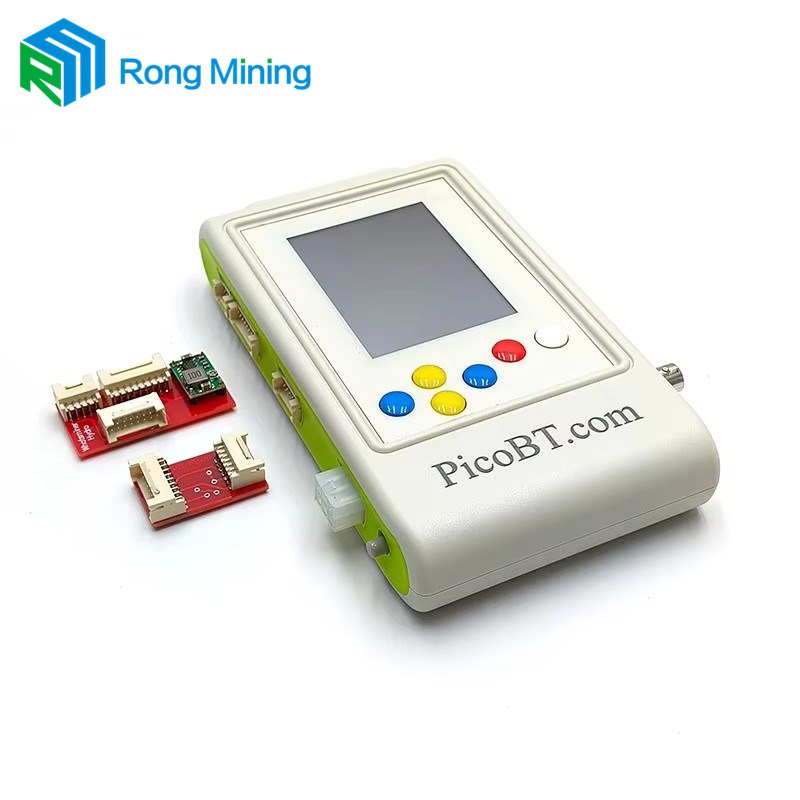
1. Understanding the PicoBT Multifunctional Hash Board Tester
A hash board is one of the most important components inside an ASIC miner. It contains multiple application-specific integrated circuit (ASIC) chips that perform the calculations required for cryptocurrency mining. If a chip fails, a signal becomes abnormal, or the board cannot receive stable power, the miner may lose performance or stop working altogether.
Traditional troubleshooting often involves checking individual components, tracing electrical signals, examining power delivery, and using separate tools for different tasks. This process can be time-consuming, especially when a workshop handles multiple miner generations and manufacturers.
The PicoBT Multifunctional Hash Board Tester combines several maintenance functions in a single device. Depending on the tester version, supported model, firmware, and required accessories, its functions can include:
One important advantage is workflow consolidation. Instead of preparing a separate test arrangement for every basic diagnostic task, technicians can use one main platform for several compatible maintenance procedures. This can help organize repairs, improve consistency, and reduce unnecessary handling of valuable hash boards.
However, a multifunctional tester is not a universal replacement for every electronic diagnostic instrument. Complex faults may still require a multimeter, oscilloscope, soldering equipment, thermal inspection, circuit documentation, and component-level testing.
2. Common ASIC Miner Problems It Helps Investigate
Mining hardware operates under sustained electrical and thermal loads. Over time, environmental conditions, unstable power, component aging, and mechanical stress can affect the performance of individual boards. The challenge is distinguishing the actual cause from the symptoms displayed by the miner.
Unrecognized or Missing ASIC Chips
When a hash board reports fewer working chips than expected, the issue may involve an individual ASIC, a communication signal, a power rail, or a supporting circuit. Compatible PicoBT test modes can help technicians assess chip detection results and narrow the area requiring further investigation.
Abnormal Hashrate and Intermittent Errors
A miner that operates intermittently can be more difficult to diagnose than a completely failed unit. A weak chip or unstable signal path may cause inconsistent behavior. Repeated testing, when supported and appropriate for the selected model, can help reveal whether a fault is persistent or intermittent.
Power Supply Problems
A defective or incompatible power supply can create symptoms that resemble a damaged hash board. The miner may fail to start, reset unexpectedly, or operate inconsistently under load. Testing a compatible digital PSU separately helps technicians determine whether power delivery deserves further attention before replacing board components.
EEPROM Data Inconsistencies
Some supported miners rely on EEPROM information for board identification and related configuration data. Incorrect, missing, or inconsistent data may contribute to recognition or startup problems. EEPROM tools can assist with reading, saving, and writing supported data, but technicians should verify the cause before changing stored information.
Temperature Sensor and Signal Faults
Temperature monitoring and chip communication are important to normal operation. Depending on the miner model and test mode, diagnostic results may provide information about supported sensors or signal paths. A failed reading should be treated as a starting point for investigation rather than automatic proof that a particular chip must be replaced.
3. Three Core Functions Explained
Function One: Hash Board Testing
The primary purpose of the PicoBT is to assist with the diagnosis of supported mining hash boards. After selecting the correct manufacturer and board model, a technician can run the applicable test mode and examine the reported results.
Depending on the model, test functions may help evaluate:
- The number of ASIC chips detected compared with the expected configuration.
- Chip communication and signal behavior in supported test directions.
- Selected reset signal behavior on compatible boards.
- Available temperature sensor readings and chip identification information.
- Whether a fault requires additional component-level investigation.
These checks can be especially useful for workshops that receive boards with incomplete repair histories. Establishing a repeatable testing procedure before and after repair provides a clearer basis for evaluating whether the work has improved the board's condition.
Function Two: Compatible Power Supply Testing
Mining power supplies deliver substantial electrical power to the hash boards. A supply that cannot provide the expected output may cause startup failures, abnormal operation, or misleading board test results.
The PicoBT supports diagnostic functions for a range of compatible digital mining PSUs. Depending on the model and configuration, it can help technicians investigate output voltage and PSU-related operation without relying on a complete mining rig for every initial check.
Examples of PSU families listed for certain PicoBT configurations include Antminer APW series units, Whatsminer P-series units, and selected Innosilicon, Aixin, or Cheetah supplies. Exact model compatibility must be verified before connecting any equipment.
Function Three: EEPROM Reading and Editing
EEPROM stores information used by compatible electronic equipment. On supported hash boards, this information can include identification data and other model-specific values. The PicoBT's EEPROM functions can help technicians preserve or manage this information during authorized repair procedures.
Before writing data, save a verified backup of the original contents whenever possible. Confirm that the file belongs to the correct board type and hardware revision, and avoid copying data simply because another board appears similar.
EEPROM editing should be used only when the fault diagnosis and manufacturer-specific procedure justify it. It cannot repair damaged ASIC chips, broken traces, shorted components, or inadequate power delivery.
4. Compatibility and Model Selection
Compatibility is one of the most important purchasing and operating considerations. Mining hardware manufacturers release multiple generations of equipment, and boards that look similar may use different ASIC chips, connectors, signal arrangements, or test requirements.
Product documentation for PicoBT configurations describes support across multiple miner families, including Antminer, Whatsminer, Innosilicon, and selected Aixin and Cheetah equipment. Some configurations list support for more than 120 hash board models and over 20 digital power supply models. The actual supported range depends on the specific version, firmware, and available accessories.
| Equipment Category | Examples | What to Verify |
|---|---|---|
| Antminer hash boards | Selected S9, S17, S19, S21, T-series and other supported boards | Exact board model, revision, connector, and firmware support |
| Whatsminer hash boards | Selected M-series boards | Chip family, supported test mode, cable pinout, and input requirements |
| Innosilicon hash boards | Selected T-series and A-series equipment | Supported model entry and dedicated connection method |
| Digital mining PSUs | Selected APW, P-series, and other listed units | Exact PSU model, communication cable, and test procedure |
| EEPROM operations | Compatible Antminer and Whatsminer boards | Supported data format, board identity, and backup requirements |
A Compatibility Checklist Before Purchase
- Record the full miner model and the exact hash board designation.
- Identify the ASIC chip family and board revision when available.
- Confirm that the specific PicoBT version supports the required model.
- Check whether the correct test cable, adapter, or special fixture is included.
- Ask whether the required function needs a firmware update or programming accessory.
- Verify PSU compatibility separately rather than assuming that hash board support guarantees PSU support.
For businesses repairing multiple miner generations, a written compatibility list is often more useful than relying on a general model-count claim. It helps prevent incorrect connections, reduces setup delays, and makes it easier to plan future tool purchases.
5. How to Use the Tester Step by Step
A consistent procedure improves repeatability and reduces the risk of damaging expensive electronic assemblies. The steps below provide a general workflow; the official instructions for the exact tester version and miner model always take priority.
Step 1. Prepare a Safe Workstation
Place the hash board on a clean, stable, ESD-protected work surface. Prepare the correct cables, power adapter, and any required fixture. Disconnect the miner from its normal power source and ensure the board is safe to handle before making connections.
Inspect connectors, cables, and the board for corrosion, burn marks, damaged components, or obvious mechanical defects. Do not energize equipment that shows signs of a potentially dangerous short circuit.
Step 2. Confirm the Exact Model
Check the board label and identify its manufacturer and model. Select the matching entry on the tester. Never choose a model based only on physical appearance or a similar product name.
If the exact model is not listed, stop and confirm compatibility rather than experimenting with another model's test settings.
Step 3. Connect the Correct Test Cable
Connect the appropriate tester port to the board using the specified cable. Check connector orientation and pinout against the model-specific instructions. Connect the required tester power input and any additional approved power connections exactly as directed.
Do not assume that a connector with a matching shape has the same pin assignments. Incorrect connections can damage the tester or the board.
Step 4. Select the Appropriate Test Mode
Navigate to the correct board model and review the available diagnostic modes. Some models provide more than one mode for different signal checks or chip evaluation procedures.
Begin with the recommended standard test. Repeated testing or special signal settings should be used only when the documentation supports them and the initial results justify further investigation.
Step 5. Run the Test and Record the Results
Start the test and allow the procedure to finish. Record the expected chip count, detected chip count, any abnormal readings, and the selected mode. If an oscilloscope probe or another accessory is required, use the specified signal test point and grounding arrangement.
Keep the original results for comparison. A structured record makes it easier to identify recurring faults and verify improvements after repair.
Step 6. Investigate the Suspected Fault
If the results indicate missing chips or abnormal signals, consult the service documentation and trace the relevant power, reset, or communication path. Use appropriate electrical measurements to distinguish an ASIC fault from a supporting circuit issue.
A failed test does not automatically mean that every undetected chip is defective. One upstream fault can sometimes affect the apparent behavior of several chips.
Step 7. Verify the Repair
After completing the repair, repeat the same supported test under comparable conditions. Compare the new results with the original record. If appropriate, perform the additional checks required by the manufacturer's service procedure before reinstalling the board.
6. How to Interpret Diagnostic Results
Reading the displayed results correctly is just as important as making the connection. The meaning of individual fields varies by miner family and test mode, so the applicable manual should be used to interpret the screen.
| Observed Result | Possible Meaning | Recommended Next Action |
|---|---|---|
| Expected chip count matches detected count | The selected chip-detection check may be passing. | Complete any remaining required tests before declaring the board healthy. |
| Detected chip count is lower than expected | Possible chip, signal, power, connection, or supporting circuit fault. | Check connections, model selection, signal paths, and relevant supply rails. |
| Results vary between repeated tests | Possible intermittent connection, unstable power, or temperature-related issue. | Review the setup and investigate the source of instability. |
| Temperature reading is abnormal | Possible sensor, wiring, communication, or sensor-circuit problem. | Confirm the sensor result using the appropriate service procedure. |
| PSU test result is abnormal | Possible PSU fault, wrong connection, or incompatible test setup. | Verify compatibility and connections before performing further electrical checks. |
| EEPROM information is missing or unexpected | Possible data, communication, or board-identification issue. | Preserve existing data and verify the correct model-specific procedure. |
Why a Single Result Is Not Enough
Electronic systems can fail in several ways that produce similar symptoms. A missing chip indication may result from a damaged ASIC, but it may also be associated with a broken signal trace, a defective supporting component, incorrect test settings, or an unstable connection.
For reliable decisions, compare the test result with the board's known configuration, visual inspection, power measurements, and other relevant evidence. If the results conflict, repeat the setup checks before replacing parts.
7. Troubleshooting Common Testing Problems
The Tester Does Not Start
- Confirm that the tester's input voltage falls within the range specified for the exact version.
- Inspect the input cable, connector, polarity, and power source.
- Check the power switch and any documented startup requirements.
- Disconnect the test board and follow the manufacturer's instructions for checking the tester independently.
The Board Is Not Recognized
- Confirm the selected manufacturer and exact model.
- Check whether the correct port, cable, adapter, and fixture are being used.
- Inspect the connector for bent pins, contamination, or damage.
- Verify firmware compatibility and consult the model-specific instructions.
The Chip Count Is Lower Than Expected
- Verify that the board is connected correctly and that the test mode is appropriate.
- Check relevant supply voltages and communication signals using approved procedures.
- Investigate whether a fault in one section is affecting communication with downstream chips.
- Use an oscilloscope or other suitable instrument when the diagnostic procedure requires it.
The PSU Test Fails
- Confirm that the PSU model is explicitly supported.
- Check the correct communication cable and tester port.
- Verify the PSU's input supply and any required test configuration.
- Follow the specified procedure for interpreting output measurements.
EEPROM Operations Do Not Work as Expected
- Check that the board family and EEPROM function are supported.
- Confirm the connection and the instructions for the selected model.
- Preserve the original data before attempting any write operation.
- Do not use an unverified data file or interrupt an operation that is in progress.
8. PicoBT Versus Conventional Diagnostic Methods
Conventional repair methods remain valuable, particularly when technicians need to investigate a circuit at component level. The practical difference is how much setup is required for routine checks and whether several diagnostic functions can be handled through one compatible tool.
| Consideration | Multifunctional Tester | Separate Diagnostic Tools |
|---|---|---|
| Routine hash board checks | Provides supported model-specific test procedures. | May require manual setup and more individual measurements. |
| Power supply diagnosis | Can test compatible digital PSUs using the prescribed setup. | May require separate equipment or manufacturer-specific interfaces. |
| EEPROM management | Provides supported data operations in compatible configurations. | May require a dedicated programmer and suitable software. |
| Component-level repair | Helps narrow down the suspected fault. | A multimeter, oscilloscope, and other tools remain essential for deeper analysis. |
| Model coverage | Depends on firmware, cables, adapters, and supported models. | Depends on the technician's instruments and available technical documentation. |
| Best application | Repeated diagnostic work across supported mining equipment. | Detailed electrical investigation and specialized repair tasks. |
For a repair business handling many compatible boards, a multifunctional tester may reduce repetitive setup and help standardize routine inspections. For a specialist dealing with unusual failures, conventional instruments remain indispensable. Combining both approaches often produces the most useful workflow.
9. Best Practices for Reliable Maintenance
Maintain a Structured Repair Record
Record the miner model, board revision, reported symptom, initial test results, repair actions, and final verification results. These records help technicians recognize recurring issues and reduce repeated diagnostic work.
Keep Firmware and Accessories Organized
Maintain a list of the tester version, supported model files, cable types, and required adapters. When an update becomes available, verify the source and follow the approved update procedure. Do not assume that every new miner model is supported simply because an update has been released.
Protect Boards Against ESD and Mechanical Damage
Use an appropriate ESD-safe workstation and handle boards by their edges where practical. Avoid unnecessary connector insertions, excessive probe pressure, and contact with exposed conductive areas.
Separate Diagnosis from Repair Decisions
A failed test is evidence that further investigation is required, not automatic authorization to replace a chip. Confirm the likely cause, evaluate whether the repair is technically feasible, and consider the cost of replacement components against the value of the board.
Verify Results Before Returning Equipment to Service
After repair, perform the required checks under consistent conditions. Confirm that the board behaves as expected and that any relevant sensor, signal, or power checks are satisfactory. Follow the miner manufacturer's recommendations before reconnecting it to a complete system.
Choose Equipment Based on Your Actual Workload
When evaluating a PicoBT solution, consider the number of boards repaired each week, the miner models most frequently encountered, the time required for manual diagnosis, and the cost of additional fixtures. Xinjinyi recognizes the importance of selecting maintenance equipment that matches real workshop requirements rather than relying on model counts alone.
10. Frequently Asked Questions
Q1: What is the PicoBT Multifunctional Hash Board Tester used for?
It is a maintenance tool for diagnosing supported ASIC miner hash boards, testing compatible digital mining power supplies, and performing supported EEPROM operations. Its exact capabilities depend on the device version, firmware, model, and accessories.
Q2: Which mining hardware brands can it support?
Published compatibility information for certain PicoBT configurations includes Antminer, Whatsminer, Innosilicon, and selected Aixin and Cheetah equipment, with additional models depending on the version. Always verify the exact board or PSU model before use.
Q3: Can the tester identify a completely defective ASIC chip?
It can help identify abnormal chip-detection or signal behavior on supported boards. However, a failed chip indication does not always prove that the ASIC itself is defective. Power delivery, signal paths, supporting components, and test setup should also be checked.
Q4: Does the PicoBT require a computer for every test?
Many supported hash board and PSU testing procedures can operate directly through the tester. Some updates, programming tasks, or other model-specific functions may require additional equipment. Check the instructions for your exact configuration.
Q5: Can it test mining power supplies as well as hash boards?
Yes, compatible configurations provide testing functions for selected digital mining power supplies. The PSU must be supported, and the correct communication cable and test procedure must be used.
Q6: Is EEPROM editing necessary for every hash board repair?
No. EEPROM operations are relevant only when the diagnosis indicates a supported data-related issue or a specific service procedure requires them. They cannot resolve physical chip damage, broken traces, or defective power components.
Q7: Why does a board sometimes show different results during repeated tests?
Possible causes include unstable connections, intermittent signal faults, power irregularities, temperature-related behavior, or an unsuitable test configuration. Check the setup and follow the recommended procedure before concluding that a particular component has failed.
Q8: What accessories should be checked before purchasing?
Confirm the required hash board cables, PSU communication cables, power adapter, any model-specific fixtures, and optional diagnostic probes. Also verify whether firmware updates or programming accessories are needed for your intended models.
Q9: Can a PicoBT tester replace a multimeter or oscilloscope?
No. It can streamline supported diagnostic procedures, but a multimeter, oscilloscope, and other suitable repair tools may still be necessary for component-level fault finding and electrical verification.
Q10: How can a repair workshop get the best results from the tester?
Use the correct model selection, follow the official connection instructions, record initial readings, preserve EEPROM data before editing, and repeat relevant tests after repairs. Consistent procedures improve traceability and help prevent avoidable mistakes.
Conclusion: A More Organized Approach to ASIC Miner Repair
Effective mining hardware maintenance depends on identifying the real cause of a failure before committing time and money to repairs. The PicoBT Multifunctional Hash Board Tester brings several useful diagnostic functions together, helping technicians investigate supported hash boards, check compatible digital power supplies, and manage EEPROM information when necessary.
Its practical value comes from combining suitable model coverage with correct connections, consistent testing procedures, and informed interpretation of results. It does not eliminate the need for technical knowledge or advanced diagnostic instruments, but it can make routine maintenance more structured and efficient.
For mining farms, repair centers, equipment distributors, and maintenance professionals, the best approach is to evaluate compatibility carefully, select the right accessories, and establish a repeatable workflow that prioritizes safety and verifiable results.
Looking for a Suitable Mining Hardware Testing Solution?
Choosing the right diagnostic equipment can help your team reduce unnecessary troubleshooting, improve repair consistency, and manage ASIC miner maintenance more effectively. Xinjinyi understands that every repair operation has different equipment requirements, model coverage needs, and service priorities.
Whether you are equipping a new repair workshop, upgrading your existing testing process, or comparing multifunctional hash board testing solutions, contact us to discuss your application, compatibility requirements, and maintenance goals. Our team can help you identify the key specifications to review before making a purchasing decision.