

What Are the Key Performance Limitations of Micro Thermoelectric Coolers for Optoelectronics in Extreme Temperature Environments
2026-08-24
For engineers and system designers working with laser diodes, optical transceivers, and LiDAR modules, the thermal management challenge intensifies when ambient conditions swing from -40°C to +85°C or beyond. Micro Thermoelectric Coolers for Optoelectric (also known as micro-TECs) are often the preferred active cooling solution due to their solid-state reliability, fast response, and precise temperature control. However, when deployed in extreme temperature environments—such as aerospace, automotive under-hood, or outdoor telecom cabinets—these miniature Peltier devices face distinct performance ceilings. At X-Meritan, we have tested hundreds of micro-TEC configurations across harsh thermal profiles, and this blog dissects the real-world limitations that impact optical system stability, lifetime, and energy efficiency.
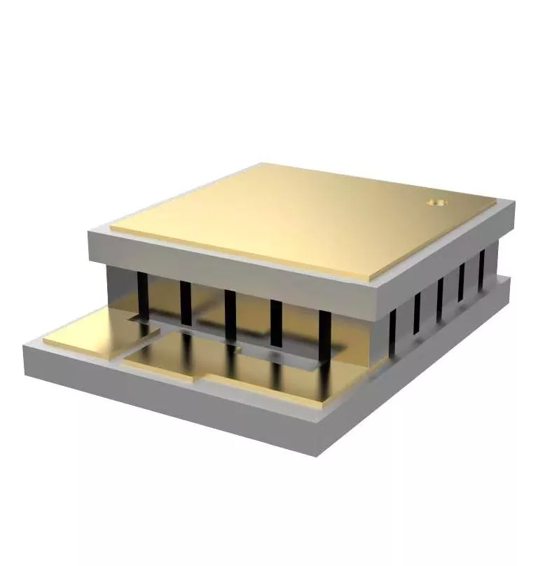
1. Maximum Temperature Difference (ΔTmax) Collapse
The single most cited specification for Micro Thermoelectric Coolers for Optoelectric is ΔTmax—the maximum achievable temperature difference between the cold and hot sides under zero heat load. In standard room-temperature conditions (27°C hot side), a high-performance micro-TEC may achieve ΔTmax of 70–75°C. However, in extreme hot environments (e.g., 85°C ambient), the hot side temperature rises, and the cold side can no longer reach cryogenic levels. The figure of merit (ZT) of bismuth telluride-based materials degrades exponentially with increasing mean temperature. Practically, this means:
-
At +85°C hot side, ΔTmax drops to 45–50°C, leaving only 10–15°C of active cooling headroom for a 0°C target.
-
At -40°C cold side, the Peltier effect weakens due to reduced carrier mobility, making it difficult to maintain stable laser wavelength.
2. Coefficient of Performance (COP) Degradation
COP is the ratio of cooling power to input electrical power. For Micro Thermoelectric Coolers for Optoelectric, COP is already low (typically 0.3–0.6) compared to mechanical compressors. In extreme thermal environments, COP plummets further:
| Ambient Condition | ΔT Required | Input Power (W) | Cooling Power (W) | COP |
|---|---|---|---|---|
| 25°C (baseline) | 40°C | 2.5 | 1.0 | 0.40 |
| 85°C (hot) | 50°C | 4.2 | 0.9 | 0.21 |
| -40°C (cold) | 30°C | 1.8 | 0.5 | 0.28 |
This COP collapse forces designers to oversize power supplies and heatsinks, negating the size advantage of micro-TECs. At X-Meritan, we recommend derating cooling capacity by 40–50% when specifying micro-TECs for military or automotive grade optoelectronic packages.
3. Thermal Fatigue and Solder Joint Cracking
Extreme temperature environments are not steady states—they involve rapid thermal cycling (e.g., -40°C to +125°C within 15 minutes per AEC-Q100 standards). Each cycle induces mechanical stress between the ceramic substrates, thermoelectric legs, and solder interconnects due to mismatched coefficients of thermal expansion (CTE). Over 500–1000 cycles, microscopic cracks propagate, increasing electrical resistance and reducing heat pumping efficiency. For Micro Thermoelectric Coolers for Optoelectric, the failure mode is often gradual: ΔTmax declines by 5–10% after 2000 cycles, and some legs may detach entirely. X-Meritan addresses this with advanced underfill materials and CTE-matched alumina substrates, but the intrinsic material limitation remains a key barrier.
4. Reduced Heat Rejection Capacity of the Hot Side
The hot side of a Micro Thermoelectric Cooler for Optoelectric must reject both the absorbed heat from the optical component and the Joule heat generated by the Peltier device itself. In high-ambient environments, air-cooled heatsinks lose efficiency because the air-to-ambient temperature difference shrinks. Liquid cooling is impractical for many compact optoelectronic modules. Consequently, the hot side temperature rises above ambient, further reducing ΔTmax and accelerating COP decay. This creates a positive feedback loop: more current is applied to maintain cooling, which generates more Joule heat, worsening the hot-side condition.
5. Material ZT Saturation at Extremes
Bismuth telluride (Bi₂Te₃) alloys—the dominant material for Micro Thermoelectric Coolers for Optoelectric—have a peak ZT around 50–100°C mean temperature. Below -20°C or above 120°C, ZT drops by 30–40%. Emerging materials like skutterudites or half-Heuslers offer better high-temperature performance but are difficult to microfabricate into thin-film or bulk micro-pillars. Until commercial manufacturing matures, existing micro-TECs will inevitably underperform in extreme cold-start or desert-environment deployments. X-Meritan actively monitors these material advances, but for current production, we advise customers to use dual-stage or cascade micro-TECs for ΔT requirements exceeding 60°C in harsh ambients.
6. Response Time vs. Thermal Mass Trade-off
Optoelectronic devices, especially tunable lasers and avalanche photodiodes, require fast temperature settling (< 1 second). In extreme environments, the thermal mass of the micro-TEC plus the optical submount increases the time constant. Moreover, the PID controller must adapt its gain because the system’s thermal impedance changes with ambient temperature. Many standard commercial drivers fail to stabilize within spec when ambient swings rapidly. At X-Meritan, we provide application notes on feed-forward compensation, but this is a system-level limitation that cannot be solved by the cooler alone.
FAQ – Common Questions About Micro Thermoelectric Coolers for Optoelectric in Extreme Conditions
Q1: Can I increase the cooling power of a Micro Thermoelectric Cooler for Optoelectric by simply raising the input current in hot environments?
A1: No. Raising the current increases Joule heating (I²R loss) more than the Peltier cooling effect beyond the optimal current point (I_opt). In hot ambients, I_opt actually decreases because the hot-side temperature rises, reducing the Seebeck coefficient. Operating above I_opt leads to negative net cooling—the cold side warms up instead of cooling down. For example, a typical 6A-rated micro-TEC may have I_opt = 4.5A at 25°C, but at 85°C ambient, I_opt drops to 3.8A. Always consult the ΔT-I-V curves provided by the manufacturer, and consider using a current-limited driver with temperature feed-forward compensation. X-Meritan provides detailed derating charts for all our micro-TEC models covering -55°C to +125°C.
Q2: How do I predict the lifetime of a Micro Thermoelectric Cooler for Optoelectric when subjected to daily thermal shocks from -40°C to +80°C?
A2: Lifetime prediction requires combining Coffin-Manson fatigue models for solder joints with Arrhenius-based degradation of the thermoelectric legs. For a typical 2.5 mm × 2.5 mm micro-TEC with 128 couples, accelerated testing (1000 cycles, 15-minute dwell) shows a median time-to-failure (MTTF) of approximately 12,000 cycles at ΔT = 50°C. However, if the temperature swing exceeds 100°C, MTTF drops to 3,000–4,000 cycles. To estimate your specific use case, measure the actual hot-side temperature swing (not just ambient) and the electrical current duty cycle. We recommend adding a soft-start current ramp (50 ms) to reduce instantaneous thermal stress. X-Meritan offers a free lifetime estimation tool upon request, based on our proprietary database from 15,000+ test hours.
Q3: Are cascade or multi-stage Micro Thermoelectric Coolers for Optoelectric always better for extreme cold environments?
A3: Not always. Cascade micro-TECs (two or three stages stacked) can achieve ΔT > 100°C, which is beneficial when your optoelectronic chip must be held at -30°C while ambient is +60°C. However, cascade designs have three major drawbacks: (1) they are 3–5× thicker (1.5–2.5 mm vs. 0.5–0.8 mm for single-stage), which may violate height constraints in compact optical subassemblies; (2) their COP is even lower (0.1–0.2) because each stage consumes power and the middle stage must reject heat from the cold stage; (3) their response time is slower due to higher thermal mass. For applications requiring only 30–40°C of active cooling, a well-optimized single-stage Micro Thermoelectric Cooler for Optoelectric with high-ZT material and low-resistance solder is more reliable and cost-effective. X-Meritan engineers can simulate both single and cascade options using our thermal FEA models to match your exact ΔT and footprint requirements.
Summary Table – Key Limitations at a Glance
| Limitation Factor | Effect at Extreme Heat (85°C) | Effect at Extreme Cold (-40°C) | Mitigation Strategy |
|---|---|---|---|
| ΔTmax collapse | ↓ 30–35% | ↓ 15–20% (cold side) | Use cascade or reduce target ΔT |
| COP degradation | ↓ 40–50% | ↓ 25–30% | Optimize I_opt; use PWM control |
| Thermal fatigue | Cracking after 1k–2k cycles | Similar, plus brittle failure | Underfill; CTE-matched ceramics |
| Hot-side rejection | Air-cooling insufficient | Not applicable | Liquid assist or forced air |
| Material ZT drop | ZT ↓ 30% at 120°C | ZT ↓ 20% below -20°C | Wait for advanced materials |
| Response time | Slower due to low ΔT | Faster, but overshoot risk | Adaptive PID + feed-forward |
Final Recommendation
Selecting Micro Thermoelectric Coolers for Optoelectric for extreme temperature environments demands a holistic view—not just datasheet ΔTmax, but also thermal cycling endurance, COP at operating point, and system-level heat rejection. Over-specifying current or ignoring hot-side thermal resistance are the two most common pitfalls we observe. At X-Meritan, we combine in-house material characterization, accelerated life testing, and customized mechanical designs to match your optical package exactly—whether it is for space-grade interferometers or under-hood 1550-nm LiDAR.
Contact Us – If you are facing cooling challenges with your optoelectronic system in harsh climates, reach out to our thermal engineering team. We provide free thermal simulations, sample testing under your actual environment profile, and fast-turnaround custom micro-TEC assemblies. Visit our website or email us directly to discuss your project requirements—we will respond within 24 hours with a preliminary solution and performance guarantees. Let X-Meritan be your partner in reliable, extreme-environment optoelectronic cooling.